Opening Up Your PSP and Removing Parts
The following tells you, step-by-step, how to open up and remove the main parts of your
PSP.To put your PSP back together, just perform these steps in reverse order.
PSP.To put your PSP back together, just perform these steps in reverse order.
Step 1: Prepare the PSP
Be very careful working with your PSP. Just like a medical operation, you need to take precautions.
The first step is to place the PSP face down on the electrostatic mat or white towel (only
if there’s no static), and to put on your static wrist strap and ground it appropriately. Using the
mat or towel prevents scratches to the PSP’s plastic screen cover.
Remove any Memory Stick and UMD game cartridge you have loaded, and remove the battery
from your PSP.
below is a diagram of the locations of the screws on the backplane and battery compartment.
Print this diagram and when you remove a screw, place it on the diagram on a flat surface
far enough from where you’re working (and away from pets) so you don’t bump into it.
Using a little bit of two-sided tape can help as well, keeping the screws in place, but that’s generally
overkill as long as you’re careful.
Step 2: Remove the Back Plane
The PSP’s back plane (the side with the word PSP in a circle) is your doorway to the insides of
your PSP. You’re going to need to remove the battery cover to complete this step. Note that
some of the screws are covered by a sticker, which you will have to move out of the way or
remove altogether to access. However, removing that sticker likely voids your warranty, so be
prepared.
You need to remove eight screws with your Philips head screwdriver. The screw holes have a
very narrow radius, so this is where the thin shaft of the screwdriver and the magnetic tip come
into play. Make sure you don’t strip the screw heads.
Once you’ve removed all the screws (don’t leave them loose in their sockets), gently separate the
backplane from the cover. At this point the clear Left and Right triggers (marked as L and R)
may come out— that’s okay, because they rely on the case being together to stay where they
are. You can safely leave them off and just slide them back into place when you put your PSP
back together (you’ll see the grooves they slide into).
Put the faceplate away in a safe location, face-up, so you don’t scratch the plastic, and put the
PSP face-up in front of you. You should now see the guts of your PSP,
including the screen, the bottom button bar, what that slick analog stick looks like underneath,
and your arrow and shape button contacts.
If you have to put the L and R buttons back in when putting your PSP back together, make sure
they move like they did before. When they are properly in place, they will move like they’re supposed
to (like triggers). You know you’ve got it wrong if they don’t have any spring action when
you press them—in that case, just reseat them and make sure they’re in the proper grooves
on your PSP.
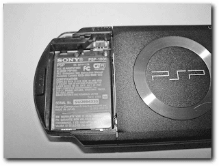
The last screw hides under a warranty-voiding sticker
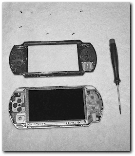
The first layer of PSP guts
Step 3: Remove the Metal Button Bar
Now that you’ve removed the faceplate and can see the guts of your system, it’s time to remove
the screen. In order to do this you’re first going to have to remove the metal button bar on the
bottom of the device
Now that you’ve removed the faceplate and can see the guts of your system, it’s time to remove
the screen. In order to do this you’re first going to have to remove the metal button bar on the
bottom of the device
To remove the metal button bar, simply pry a little on the metal catch to left of the bar and
very gently lift it out at an angle. It is connected to the PSP’s mainboard by a circuit strip connector.
You need to very carefully move the circuit strip connector up with the flat-blade screwdriver
so you can pull the circuit strip out of its holder (the tan tab). Remember which side was
up when you pull the circuit strip out or the button bar won’t work when you put it back in.
Step 4: Remove the Screen
Now that you’ve removed the button bar, you can remove the screen. This part’s a little tricky
because you don’t want to crack the screen or bend any metal. Patience and gentleness are
virtues during this entire process—your PSP is at stake here!
On the bottom-left corner of the screen is a metal piece in between the analog stick controller
board and the display, making up part of the metal border of the screen.Wedge the thin flatblade
screwdriver into that crevice and the metal wedge should pop up and out a little bit. Do
the same on the top-left, and now you should be able to carefully wiggle the screen out. Be very
careful; do not bend the display or pry too hard or you may crack the LCD panel or irreparably
bend the metal—hence the reason for the very thin precision flat-blade screwdriver.
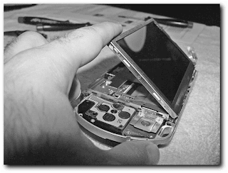
To remove the screen completely, you have to remove more circuit strips (and pay attention to
which angle you had to open their catches and which way the circuit strip goes in). The long
connector on the left lifts from the bottom, while the shorter one on the right lifts from the top
which angle you had to open their catches and which way the circuit strip goes in). The long
connector on the left lifts from the bottom, while the shorter one on the right lifts from the top
Once you have removed the screen, place it face-down on a towel to prevent scratching.
Preferably, you should put it somewhere it won’t fall onto a hard surface.
Preferably, you should put it somewhere it won’t fall onto a hard surface.
Step 5: Remove the Metal Screen Holder
Now that you removed the display, you need to remove the metal display holder so you can
access the PSP’s mainboard.To do this, you need to remove the nine remaining screws with the
precision Philips-head screwdriver. After you have removed each screw, place it in the appropriate
position on your copy of the screw location diagram. In addition to the screws, the metal
screen holder is held in place by the release switch for the UMD drive. Gently slide it to the
right to release its grip on the metal, then all you have to do is gently lift out the display holder
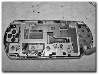
The metal screen holder with the nine screws removed
Step 6: Carefully Remove the Circuit Strips
Now that you’ve removed the screen holder, you need to get to the mainboard. You need to
remove the circuit strip connecting the UMD drive to the mainboard. Be very careful, as the first time I did this the solder was weak the circuit strip holder
actually came off the mainboard! Then remove the power plug at the top left, but not the small
ones on the bottom of the board, while continuing to be careful not to break any wires or
solder.
Once you disconnect the cables, you may still have one more step to complete depending on
how your PSP was made. You may see the black wireless antenna cable running alongside the
top of your PSP . Gently remove this from the groove it runs through on the
top left of the mainboard so you can successfully remove the mainboard.
how your PSP was made. You may see the black wireless antenna cable running alongside the
top of your PSP . Gently remove this from the groove it runs through on the
top left of the mainboard so you can successfully remove the mainboard.
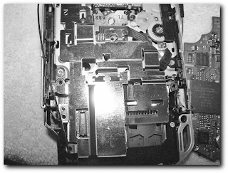
The PSP’s wireless antenna
Step 7: Remove the Mainboard
Now that the cables are out of the way, gently lift up the mainboard and put it aside. If you take a look at the mainboard, you’ll see the ARM-based processor Sony
uses, their graphics chip and USB controller, as well as many other items.
Now that the cables are out of the way, gently lift up the mainboard and put it aside. If you take a look at the mainboard, you’ll see the ARM-based processor Sony
uses, their graphics chip and USB controller, as well as many other items.
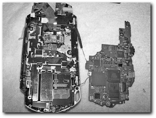
The mainboard successfully removed
All this work and you’re still not at the Wi-Fi interface yet! (I sure wish Sony had made this
easier.) To get to the final piece, the Wi-Fi card, you need to remove the shielding plate by
using your precision Philips-head to remove the three remaining screens holding it in place
easier.) To get to the final piece, the Wi-Fi card, you need to remove the shielding plate by
using your precision Philips-head to remove the three remaining screens holding it in place
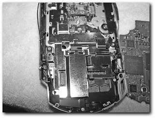
The screws holding the Wi-Fi card in place
Step 9: Remove the Wi-Fi + Memory Stick Board
Now here’s the final piece: the Wi-Fi communications board, which also houses the Memory
Stick interface, as shown in Figure 4-16. You can remove this piece if you like and see an
entirely gutted PSP, or just start putting things back together (good thing you have those screw
diagrams!) or fidgeting around. Note that the Wi-Fi board has a socket connector, making
upgrading or replacing the antenna fairly easy (well, besides the PSP disassembly step), . Appendix A has a link to an online project to add an external wireless
antenna. If you’ve come so far that you’re at the Wi-Fi + Memory Stick board, feel free to
try that project. I did not discuss it in detail in this book because most people may not take
apart their PSP so fully (there’s usually no reason other than for exploratory purposes).
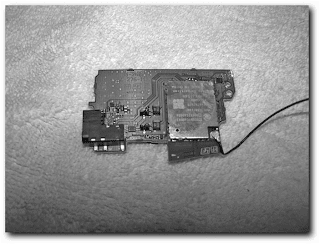
The PSP’s Wi-Fi board, Memory Stick interface, and antenna socket connector
Knowing
how the PSP ticks on the inside is important for any hardware hacks you may want to attempt,
including fixing your PSP yourself when sending it to Sony is not an option.
how the PSP ticks on the inside is important for any hardware hacks you may want to attempt,
including fixing your PSP yourself when sending it to Sony is not an option.


0 comments:
Post a Comment